In my first blog on Common VRF (Variable Refrigerant Flow) Installation Issues I focused on issues during mechanical and hardware installation that typically lead problems during startup and pre-functional checkout commissioning. This blog will focus on controls issues identified during commissioning design review which usually lead to issues during start up if not addressed up front during design. As mentioned in the previous article, VRF systems can allow for better comfort and overall satisfaction, but if not properly programmed for the owner’s specific application, can lead to numerous complaints during the first year of occupancy.
VRF Controls
One of the benefits of VRF is they offer a tremendous amount of controllability for the owner and the occupants; however, if the owner is not properly trained and the initial system programming isn’t completed per the specified sequence of operations there can be multiple complaints during the start of occupancy. VRF system controls can be broken down into two main components: central control, and local control. The local control is what the occupants use to adjust space temperature set-points and other functions of the local VRF indoor unit. The central control allows the user to control all indoor units of a given system, or group of systems, via a web interface or centrally mounted controller. Overall, a VRF system controls itself to maintain given set-points via pre-installed proprietary programming. You can think of it as if the brains of the system are built in, and the controls for the system just tell the brain what to control.
Figure 1: VRF Controls Layout
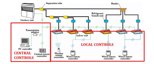 (Photo Credit: https://www.researchgate.net/figure/Components-of-VRF-systems_fig2_312182469)
Specifying VRF Controls
Specifying standalone VRF controls can be a challenge due to the fact the engineer and ultimately the installing contractor is limited to controlling the VRF system via the local or central controls commands. Typical commands required from the local or central controls for the VRF system to operate with include:
- Space temperature set-points
- Indoor unit fan speed
- Indoor unit louver position
- Indoor unit control prohibit (lockout local users from changing set-points)
- Indoor unit mode (i.e. Cool, Heat, Auto, etc…)
Instead of providing a typical terminal unit controls sequence that a controls contractor can then implement, a VRF system already has these sequences built in, and it is the responsibility of the installing contractor or controls contractor to send commands to achieve the desired sequence. The engineer then becomes responsible for specifying the commands (mode, fan speed, louver position, etc.) that the controls system needs to send to the system. An example for a specified sequence of operation for a VRF indoor unit might be: “unit shall control to maintain space temperature using integral controls in the automatic heat/cool mode, with the louver and fan speed control in automatic mode.” Additional details should be addressed, such as local controls/thermostats being locked out to prevent users in certain zones from changing any settings, or combination of settings.
If a VRF system will be integrated to a DDC it allows for a little more flexibility, but ultimately the DDC contractor is at the mercy of what is available for commands from a particular VRF system. For example, a DDC sequence could be implemented that tells a VRF system to go into cooling mode at a space temperature of 72F and heating mode at 67F, but it’s not as straight forward as that. Either a controls interface accessory needs to be provided to allow the DDC to send simple cooling and heating commands, or the programming needs to include a set-point when sending the command to the controls, i.e. “system to cool to a 72F setpoint when entering cooling mode, with fan on high and louver at highest position.” This is just one example of how details of both sequences and hardware need to be thoroughly vetted during design to ensure a system is capable of operating per the owner’s requirements.
VRF systems often times are associated with additional equipment to provide auxiliary or back up heating. This is another crucial piece of programming and hardware that needs to be identified during design, it can be done via VRF system controls, or DDC. VRF systems are often capable of enabling an auxiliary heating source through the systems hardware, but may require additional hardware, controls, or specific indoor units to accomplish it. This can also be accomplished through DDC, however, the DDC will need to read specific points from the VRF system to enable the heating.
It is extremely important for the manufacturer’s representative to be involved during this process to ensure that the VRF system has the ability to provide the control requirements being sought by the owner, and if it cannot be achieved, offer alternate options to most closely meet the requirements.
Next Steps: Implementation
Following the steps outlined above during design will provide the construction team with robust construction documentation for programming a system that meets an owner’s requirements. In a following blog post I will discuss additional steps to be taken during implementation of VRF controls to ensure owner satisfaction. Contact Cx Associates to see how we can help with commissioning of your VRF project.