Note: This is Part Two in a series of posts on RS-485. | Part 1 | Part 3
In Part One One of this series of posts on RS-485, I gave a high level introduction to the structural and electrical components of RS-485 networks. This week I’ll elaborate on those concepts and delve a little more deeply into some of the industry terminology and how it applies to those concepts. As always, please feel free to drop a comment if you have any questions or want further discussion on any of this information.
Terminology – Talk the Talk
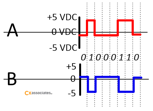
Let us pick up where we left off by covering some of the terminology. I left off Part One with a short look at baud and how electricity is converted into data (bits). What is baud? Let's take a step back. First off, it’s very rare that bits are predictable. This is because network communications are based upon unpredictable events occurring in the real world outside the network. For instance, let’s say we want to send a temperature value. Temperature values are always changing because the temperature of a room, or the temperature measured inside an air conditioner (often referred to as an Air Handler in commercial buildings) is never constant. One moment a temperature sensor can read 70.0 degrees in a room, a second later it can change to 70.1. I know that can seem like a non-trivial event, but to a computer system, any change of temperature can result in some information being sent over a network. To keep things simple, let’s just encode the 70 electrically. Just the raw number 70 (with no decimal) in binary looks like this: 0100 0110. So electrically it looks like this:
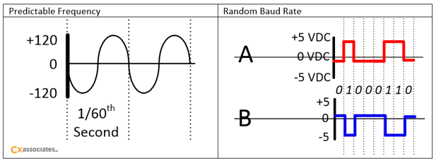
 You can now see that there is a large chunk of the signal that is flat (or unchanging), because of all the zeros required to represent the number 70. This is where baud comes back into play. Think of baud as being almost the same thing as a frequency. Whereas frequency can be defined as the rate at which a signal cycles in an ordered pattern (or an oscillation). Therefore, with frequency, you can predict what the next signal is going to be if you are reading the current signal in real-time. Take AC power from your outlet for example. It alternates between positive and negative 120 volts 60 times a second (or 60 hertz). From the negative 120 volts' portion of the total cycle, it always goes to the positive 120 volt portion of the cycle and vice versa. If you freeze time, and you measure -120 volts, you know for a fact it’s going to go positive next.
With baud, you’re still talking about a signal change at a particular rate (noted in “signal changes per second”) but you cannot predict what the next signal will be as it represents encoded information which is generated in an unpredictable way (generally in reaction to sensors on a controller, like a room temperature sensor). Baud is important to understand because it is how the computers can determine consecutive bits of the same value are coming down the wire. Since the baud is known by all the computers on the network, that interval is used to cut out (or rather sense) consecutive bits (which would all have the same voltage) coming down the wire if the voltage remains unchanged.
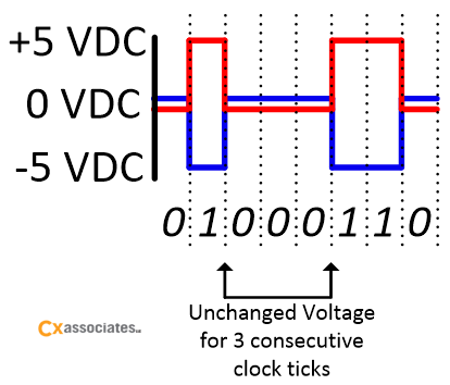
In the above example, the computer will measure three consecutive zeros in the middle of these 8 bits representing our data (the number 70). For another example to drive this home, say we just look at this signal but we don’t know what the baud is:
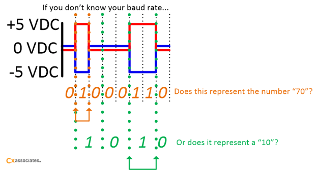 Just by looking at the signal changes, it’s hard to determine if the value coming down the wire is a series of bits representing the number “70” or a series of bits representing the number “10” (which in binary is shown below the 70). You could argue that the bottom baud (shown in the green dotted lines) is ½ the speed of the top one (shown in the orange dotted Line).
This illustrates the problem that occurs when two or more computers (or BAS devices) have different bauds on the same wire! This occurs frequently in the real world (no pun intended). Some protocols have means of dealing with this on the fuzzy boundary between the electrical standard and the protocol (often called the Media Access Control layer – or MAC for short). Some controls use what is called a “preamble” to let other controllers on the network know what baud rate they are using. A preamble is simply a string of alternating 1’s and 0’s of a known bit-length (say 16 or 32) that allow other controllers to sync their clock to the clock of the computer about to send data. By sending this preamble, any network using a “non-return to zero,” or NRZ, encoding can increase the chances of a particular receiving device being in sync with the baud of the sending device.
Baud also has some of the physical side effects that any electrical signal (repetitive or not) induces on a wire. These side effects can create big problems with BAS systems and their communications reliability. That’s why we use twisted shielded cables, low impedance wire, biasing resistors, and end of line resistors. All of these requirements help fight the physical interference created by a pulsing electrical signal being propagated over some distance of wire.
Impedance – “Bubbles” On a Wire
Another important term related to baud is impedance. I’m going to describe how baud can affect impedance. You may remember the basic science behind electromagnets from school. Basically, any time you send electricity down a wire, that wire becomes magnetized to a certain extent. Sometimes, in school, they would use iron filings to help you visualize what those magnetic fields looked like. It generally looked something like this:
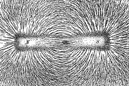 Image source: https://upload.wikimedia.org/wikipedia/commons/5/57/Magnet0873.png
Every time you electrify a wire, you get a magnetic field. The funny stuff happens when you reverse the polarity of that wire at a rapid rate (at your baud!). This is because you can think of that magnetic field as a bubble. That’s right, a bubble. Think of this:

Right away you can see how magnetic fields look like bubbles. You can also think of them as expanding and collapsing as a bubble that was never completed (or let go from the wand, so it still has that hole in it you inflated the bubble through). To see this in action, try this fun at-home experiment with the kids: blow a bubble through a typical bubble wand, but without allowing it to form all the way, as shown above. If it never leaves the wand and completely forms a bubble, and you stop blowing, it will collapse and actually blow the air which fills it back at your face. This is the same thing that happens to a long length of wire carrying a pulse of electricity. As the electrons move down the wire, they build an electromagnetic field (a “bubble” of magnetism) along the length of the wire. When the pulse of electric current stops being powered, and the flow of electrons stops, the bubble of magnetism stops expanding, and actually collapses. This causes a reverse flow of electrons along the wire while the field collapses, much like a collapsing bubble will push the air blown into it back out the opening in the wand that formed it.
This reverse flow is not as strong as the initial current (or as the air pressure that formed the bubble in the first place), but still occurs until all the energy is dissipated (until the bubble is completely collapsed). This reverse flow can interfere with devices in the network and make them artificially read a “1” or “0”. It can also cause interfere with the voltage on the wire causing “1”s and “0”s to be misread or not read at all. This is a function of the wire’s length and is essentially the phenomenon referred to as impedance. However, in digital networks, we call it crosstalk because those field collapses are as intermittent in nature as the data coming down the wire. Also, because there are at least two wires, there is an induction from one wire to another during these field expansions and collapses. So the interference is just as intermittent as the data being sent down the wire.
So how do you combat such a phenomenon you ask? First line of defense, twisted wire! We twist the wire in a way such that the number of twists per inch actually interfere with the physical magnetic fields that are constantly expanding and collapsing with the pulses of electricity moving down the wire. If we twist the wire, we cause those collapsing magnetic fields to fight each other and thus induce less current as they collapse. It’s like (in keeping with the above analogy) twisting the bubble as you blow it so that when you stop blowing, it just busts instead of pushing all the air trapped inside back out the wand opening. The second line of defense: lower your baud rate.
Longer RS-485 Networks Require Slower Baud
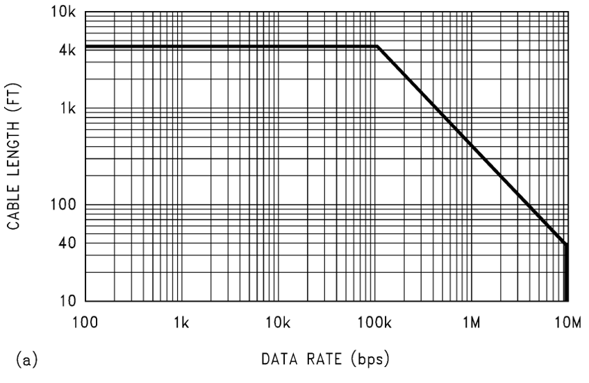
The main take away is that the longer the RS-485 network is physically, the slower your baud must be due to some of these physical side effects described above, mainly cross talk and capacitance (how big the bubble is you’re creating magnetically). Figure 4 in the application note “10 ways to bullet proof RS-485” put out by Texas Instruments, sums it up nicely:
 Graph source: 10 ways to bullet proof RS-485 by Texas Instruments, Inc.
As you can see in this diagram, as the cable length gets longer than about 40 feet, baud begins a steady decline from about 10 Mbps down to about 100 kbps at cable lengths that are. This is why most BAS controllers limit their baud to just under 100 kbps – so that the installers can work with up to 4,000 feet of wire which is plenty in most applications.
Next Time – When Things Go Wrong!
After covering the basics of RS-485 in Part One, and delving a bit more into baud rate with respect to impedance this week, we start to have all the understanding we need to start analyzing issues encountered with BAS networks that use RS-485 when things go wrong. My next post will cover the misconceptions of controls networks, and installation mistakes I commonly encounter. I’ll provide you a basic set of red flags you can use to determine if you have a network installation problem instead of the common scape goat – software problems. If you have any questions or comments, please feel free to drop a comment on either section of this multipart post!

