Note: This is Part Three in a series of posts on RS-485. | Part 1 | Part 2
In part 1 and part 2 of this series on RS-485 we covered the basics. Let’s take some of that knowledge and talk about what most often goes wrong with RS-485. I want to give you the ability to red flag common mistakes and some knowledge that will help repair the most common issues. I am going to take some of the knowledge we gained from the last two posts and put it into context for both existing RS-485 installations and new ones. I’ll discuss this in the form of red flags that will trigger the discussion.
Before getting into red flags, I would like to acknowledge a modification to my previous posts as suggested by a reader – that is wherever I used the term “Baud Rate” I was incorrect. The right term is simply “baud” as by definition, baud includes signal changes over time. So, by saying “baud rate,” I was being redundant and was indicating signal changes per second per second which implies an acceleration and is therefore the incorrect use of the term. (Thanks Jere for the correction!)
Let’s Start By Setting the Scene
In 2016 we are surrounded by networks. I have networked thermostats and smoke detectors in my home. I have a networked weather station. I have a cellphone that is more computer than phone, and I can use it to monitor the real-time status of pizza being made, or update flight plans when I am traveling. My point is, we have become a network-dependent society and our dependency on networks is growing by the day. When cellphones first came out, they didn’t have GPS built in, so making 911 calls was difficult, but not impossible and they saved lives. In 2016, most of us take for granted that the 911 call center would know right away how to locate us through our cell phone’s GPS. But, cell phones have varying connection strength to their networks based on your geography, and limited batteries that as the day goes on, they get weaker without recharging. Yet most of us rely on the safety of being able to call 911 from this unreliable network connection.
Red Flag 1 – A Lack of Trust in the Network
So, my first red flag to you is when your controls contractor is hesitant to depend on the RS-485 network that they install in your building. Unlike cell phones where the network dependability is based on where you are relative to other nodes in the network (cell towers), a RS-485 network is as strong and dependable as the installer. We know from part 2 that if each network is less than 4,000 feet in length, you can get up to 100 kpbs transfer rates. These speeds are more than enough for most HVAC automation applications. We know that this technology is not new and proven reliable. We know that if (like any system) a network is designed and installed correctly, it should meet the design intent correctly.
A lack of trust in the network is a red flag because they are inadvertently indicating to you that they’ve had networking problems in the past. These networking issues are generally a result of not adhering to manufacturer instructions and best practices. This can result in voltages being misread by transceivers (part 1) thus making them unable to decode the binary values being transmitted. It can also result in mismatched bauds on the same segment because a lot of devices come with an “autobaud” feature out of the box (see part 2).
When installed correctly, RS-485 is very reliable and accurate way to get modern sensors like flow stations, and space pressure monitors to share data. This is because there is no resolution loss with a digital encoded value (as shown in part 1). However if you want to take the same airflow station and hard wire it to an input on a controller, the range of the airflow station sensor has to be scaled to either a 0 – 10vdc, 4-20mA, or 0-5vdc signal. This scaling inherently causes the accuracy of that very expensive air flow station to be unnecessarily reduced. Not only that, but you’re consuming additional wiring and hardwired points for any additional sensing values (like temperature for density corrected CFM readings) that your airflow station provides.
In some cases, it makes sense to hard wire a networkable device because the value is mission critical and you want to ensure there is redundancy or you want to compartmentalize control. This means the red flag doesn’t always apply so careful consideration of the application is important. However most of the time HVAC isn’t life or death. In any building where there is critical HVAC, there is staff on hand to bypass equipment when things go wrong. Systems are engineered with redundancy and to fail safe. However, if things go right, you can save time, upfront labor costs, and energy by trusting your networked devices to talk to each other reliably just like you depend on your cell phone. If you read this thinking “I don’t depend on my cellphone” then why do you have it on you right now? What would your life be like if you didn’t have it when your tire goes flat on the interstate?
Red Flag 2 – Improper Grounding
My second red flag is when installers are haphazard about grounding. Earth grounds are important to all electrical systems. They are especially important to communications for both reliability and for stability. As previously explained in part 1, in RS-485, earth ground is sometimes the common signal reference used to measure incoming voltages. However sometimes it is not, and the manufacturer specifies you pull a 3 conductor so that the common signal reference is independent of the controller’s power ground terminal. Ultimately, grounding must be followed per the controller’s installation instructions, and they almost always state it must be the same earth ground for all controllers on the network.
Here is an example of earth grounding gone wrong:
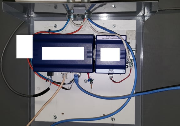
You can see in the picture here we have a Tridum JACE installed on a metal panel back plate, inside an enclosure mounted on plywood. They took the time to “ground” the JACE to the metal back plate, but they never grounded the metal back plate.
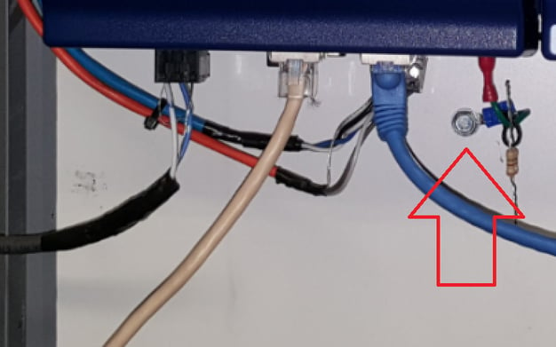
They did not ground the power supply to the JACE where the grounding terminal is clearly labeled:
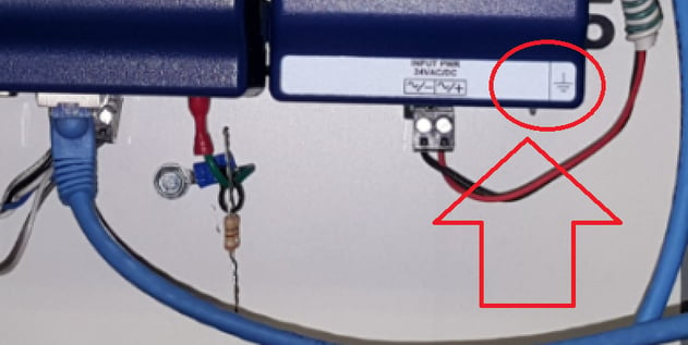
Also, they have 2 spare conductors on the 4 conductor wire pulled to supply power to the JACE. The real kicker is one of those wires is green:
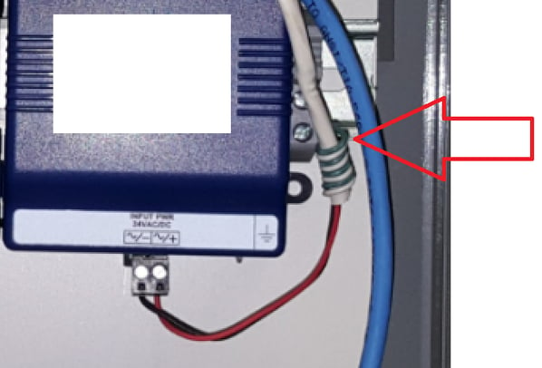
All they had to do to make this better is use that green conductor to bring the earth ground from the primary side of the control transformer’s power wiring into this panel, bond it to the metal back plane and then bond it at all earth ground terminals on both the JACE and the power supply. This is how Tridium recommends JACEs be installed by the way: https://www.google.com/search?q=Jace+installation+instructions&ie=utf-8&oe=utf-8 .
 Source: From Jace-6 Mounting and wiring instructions Published April 19, 2007 by Tridium Inc.
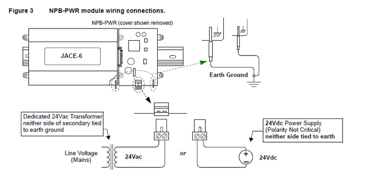
Source: From Jace-6 Mounting and wiring instructions Published April 19, 2007 by Tridium Inc.
Earth ground is also where we terminate one end of our shields so that stray interference conducted across the shield (say from cellphones and Wi-Fi) is drained to ground and not conducted across your network. Now let’s go back and see where the example installation passes or fails this test.
What was installed:

Looks like we have some incorrect shield terminations and a mix and match where on end of the segment is shielded and the other is not:
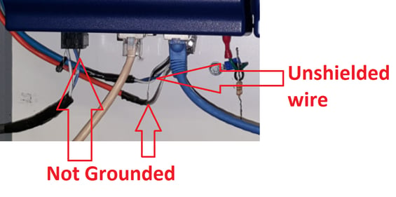 Granted, the RS-485 port to the right is in the middle of the wired network and therefore could be properly grounded at either end of the segment. However, given the port on the left, I would be suspicious and want to confirm this for myself. I would recommend if you come across this scenario, that you find the end of line devices and verify they are terminated and grounded per the manufacturer’s instructions. I would also verify which of the two wire types is correct (if either are) per the instructions.
Red Flag 3 – Improper Shielding
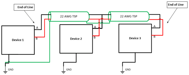
My third red flag to be on the lookout for is proper use of shielding on your RS-485 network. This is very easily tested. The first test is critical, and you may laugh at it because you’d be surprised how often this occurs. The first test is checking if the RS-485 is using twisted shielded pair (TSP) wiring. As shown above, sometimes installers run out of the right cable and they make do, which can cause serious long term problems. Always check the labeling on the wire to make sure it meets the manufacturer’s recommended specifications for capacitance, resistance, and number of conductors. The second test on proper shielding (assuming the first passed) is to check whether the shield is grounded in only one location, and maintained contiguously through the entire RS-485 segment. If you know the location of your network’s end-of-line controllers, you know that only one of them should have the shield’s drain wire connected to earth ground as shown in the ideal scenario below:
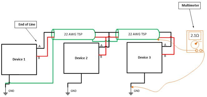
Starting at the end where the shield is not grounded, check continuity between shield and earth ground with a multimeter. You should read very low resistance to the building’s earth ground (found on conduit, or by a grounding conductor in the control panel).
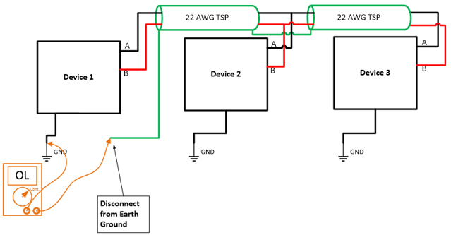
If you are at the other end of the network and you are looking at the shield’s drain wire physically connected to ground, you can perform the same test only by removing the drain wire from its ground location. This way, you are breaking the shield’s connection to ground and with a multimeter on continuity, you should read an open circuit to earth ground.
Note: On some meters “OL” as shown below means “open circuit” or no electrical connection.
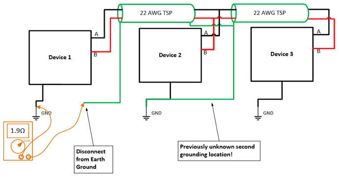
If you do not read an open circuit, that means you have more than one spot on the shield where it is earth grounded (which can lead to ground loops and cause interference). See the example below:
 These tests are very easy to perform and can identify simple problems that are cheap to repair but increase the reliability of your system’s RS-485 network. Understanding the importance of not rushing an installation of a BAS and following the manufacturer’s recommended instructions is critical to bullet proofing your network.
If you found this post helpful, feel free to drop a comment below and let me know if there are other RS-485 or controls networking related questions / issues you’d like me to address. Or you can always feel free to reach out and have us come look at your system for these types of problems if you suspect you have communication issues.

