Note: This is Part One in a series of posts on RS-485. | Part 2 | Part 3
What is RS-485 and what does it have to do with buildings or building controls? If you’re asking this question either you’re just curious, or maybe something isn’t working quite right and you’re Googling to find an answer. Either way, I plan on giving you a high level understanding of RS-485 in this post, and how having a better grip on how it works can help building operators and controls contractors control their building more effectively.
RS-485 – The Basics
RS-485 is most commonly used in non-LonWorks building automation system controller networks. The most common networks to implement RS-485 are BACnet MSTP (including the Automated Logic ARCNet implementation), Modbus RTU devices, and legacy controls networks like Johnson’s N2, Honeywell’s C-Bus, or Siebe’s ASD network.
Simply put, RS-485 is a cheap, tried and true computer networking technology. It is an electrical standard defining the electrical characteristics of most building automation networks. It was established by the Telecommunications Industry Association/Electronic Industries Alliance (TIA/EIA[1]) a long time ago as a cheap, reliable industrial networking technology. It defines how you can modulate electrical signals over a pair of wires to represent digital information (ones and zeros).
Modulate / Demodulate
 Image by Flickr user Bryan Alexander
Did I lose you at “modulate electrical signals”? Its ok – in 2016 we take for granted the number of layers our technological lives include to do even the simplest of tasks. Let’s start at modulation. If you are as old as I am, you may have used a “modem” at one point in your life. I am not sure if people still use that term, as my experience today with folks indicates they think of their internet as sourced from their Wi-Fi hotspots. The vernacular is: “my Comcast/Time Warner Wi-Fi.” That thing, that piece of equipment with flashing (hopefully green) lights, is actually a modem. Before their modern day incarnation, we had dial up modems (you know the modem that made those funny sounds after dialing a phone number?). Modems are modulators/demodulators (mo-dem). They take straight electricity from the wall, and wiggle it into 1’s and 0’s – almost literally.
Binary Communication
There are several ways this can be done, in the wired and wireless worlds. RS-485 is one standard way that defines how RS-485 types of ‘modems’ (called a transceiver – short for “transmitter receiver”) will wiggle 1’s and 0’s out of electricity to convey information between RS-485 devices. This is done over a pair of wires using direct current. An RS-485 transceiver consists of two parts:
- The part that transmits information which can be referred to as a “generator” as in signal generator, or a “driver” as in a driver of current. This is the “modulator” to tie it all together.
- The second part receives information being transmitted elsewhere, which is simply referred to as a “receiver” or the “demodulator.”
Drivers and receivers together make a “transceiver.” These are just single microchips on boards which are very inexpensive to mass produce, which is why RS-485 is commonly used in many different industries. However, not all manufacturers use the same techniques for their chips, and not all buyers of those chips use the same style of integrating them into their controllers, which is why sometimes you have a 3 wire RS-485 device or a 2 wire RS-485 device.
This is why you will see one controller like a Schneider Electric BACnet MNB-1000 that has a 3 wire RS-485 implementation where as a Schneider Electric Viconics BACnet thermostat will have a 2 wire implementation. They implement chips from different chip manufactures to accommodate their circuit boards and their respective physical size / power limitations. Technically they’re both RS-485 devices, but the instructions for the MNB-1000 Device will call for using 3 conductors on the RS-485 connector, whereas the thermostat will only want 2 conductors to be used on its connector. Let me dive deeper into how that can happen.
Two-Wire RS-485
Let’s take a look at a 2 wire RS-485 network to illustrate how the signals are modulated and demodulated on the wire. First let’s look at a single transceiver:
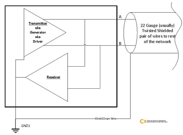 The transmitter is one triangle, and the receiver is another triangle in the diagram above. Together they represent a single transceiver. You can see that the transmitter and the receiver both share the same pair of wires (usually 22 gauge twisted shielded pair or 22 AWG TSP for short). Because of this, transmissions must be sent by only one device at a time. This is called “half duplex” communications. To understand half duplex, think of when you had a walkie talkie as a kid and both you and your friend tried to talk at the same time. Because both of you were transmitting at the same time, neither of you could receive and hear what the other was saying (this is called a “collision”). This issue can also exist in RS-485 and is usually handled by a protocol (like Modbus or BACnet). Protocols contain software rules that determine which of the transceivers on a computer network talk at what times. This is layer of software concerning who talks when is called Media Access Control (or MAC for short).
Now if we show a network with three devices:
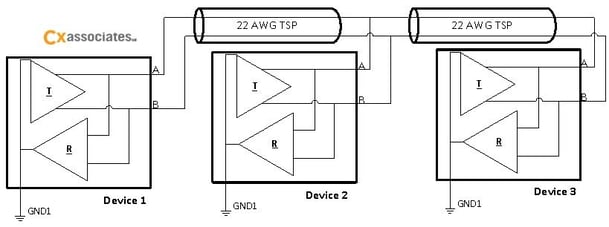 You now see how three devices are wired together. Let’s say device 1 wants to transmit a message to device 3. First, device 1 would probably check that no other devices are transmitting. This means looking on the A & B wires for some known voltage level called the “idle” voltage. This is the voltage on the wires when nobody is using them to transmit. There is a known voltage difference from idle that represents a “1” and a voltage that represents a “0.”
The Importance of a Good Ground
The way the transceivers decode the 1’s and 0’s they receive is by measuring the voltages on the wires. They measure wire A and wire B separately to a common voltage reference shared between all the devices on the network. In most cases this common reference point is earth ground on your controller. In some products, they provide you with a third terminal connection for a third wire that can be run to each device ensuring they all share the same reference point, thus ensuring that all devices always end up measuring the same voltages.
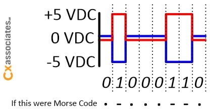
So devices pulse +5 volts on the A wire, and -5 volts on the B wire for a digital “1”. To encode a digital “0” they swap these polarities (so -5 volts on A, and +5 volts on B). When the voltage is removed, the transceivers are idle. You can think of these pulses like Morse code on a flashlight. Morse code is another binary system encoding of information that humans understand (but circuits have a hard time with). It, like all communication mediums, suffers from limitations on its physical media. If your flashlight isn’t bright enough, or your radio signal not strong enough, your message won’t get through.
In most building automation systems, I often found that controllers are not properly grounded to a common earth ground. This is the biggest problem I encounter with RS-485. It is absolutely essential in both 2 wire and 3 wire devices that (if the manufacturer’s instructions call for it and most do) the same earth ground be provided. I look for the grounding conductor provided by the 120-volt circuit supplying power to the controls transformers to be brought all the way to the controller with proper panel bonding along the way. This way, every controller in the building has a better chance of using the same earth ground[1]. This ensures your flashlight is bright enough for the Morse code to get through.
Now Electricity Becomes Data
To send an alternating sequence of eight 1’s and 0’s (called bits, or a bit sequence) the RS-485 transceivers changes the voltage on the A & B wires. Again in the example below, this voltage is measured against earth ground as is the case with most building controls because our transceiver is a 2 wire device.
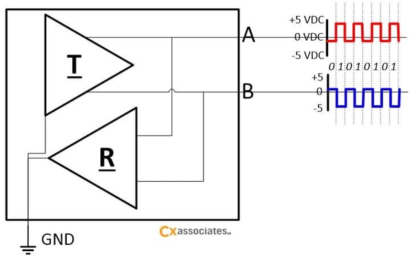
You can see that there are little dotted lines between each signal change from a 0 to a 1. These represent a unit of time called a “clock cycle.” Each clock cycle is a fraction of time based on the speed of the network, called the baud. Baud is important in building automation systems as they can both increase and decrease the speed in which a network can share data, thus impacting the reaction time of control systems. We will come back to that when we talk about encoding techniques.
In Part 2 of this post next week, I’ll get into some of the terminology used with RS-485, the importance of baud and its effects on RS-485 networks, and will discuss how we interpret 1’s and 0’s from electricity via encoding. Stay tuned. (Feel free to subscribe to our blog at the top of this page so you never miss a post - emails go out about once a week and you can unsubscribe at any time.)
[1] The EIA no longer exists, so it’s just TIA maintaining the standard today
[2] Granted, in older buildings, or buildings with several additions there is no guarantee that the earth-ground from one addition’s power system was bonded to the earth-ground of another addition. If that is not the case, then it might be worth it to consult with an electrical engineer to determine why this is, and what a controls contractor can do to provide the same earth-ground to all the controls on an RS-485 network.