Although electronically commutated motors (ECMs) are specified in efficient buildings, and energy efficiency programs provide incentives for their installation, I only had a cursory understanding of the difference between this technology and traditional shaded pole or permanent split capacitor type motors. What makes ECMs more efficient?
 By Zureks - Own work, CC BY-SA 3.0, https://commons.wikimedia.org/w/index.php?curid=4170132
Different Types – Different Efficiencies
There are many different types of electric motors and configurations, but there are three types used mainly in HVAC and refrigeration applications: shaded pole (induction), permanent split capacitors (brushed DC), and electronically commutated motors.
|
Motors |
Efficiency Range |
|
Shaded Pole (Induction) |
15-25% |
|
Permanent Split Capacitor (Brushed DC) |
30-50% |
|
Electronically Commutated |
60-75+% |
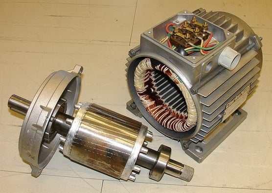
All three motor types use a fixed ring of electromagnets (stator) to induce a rotating magnetic field that pushes against an opposing field generated by separate set of electromagnets suspended within the ring (rotor). There are two sets of wires wound tightly around the stator and the rotor to generate opposing magnetic fields when electrical current passed through them. These are called the windings. The windings in the stator are stationary and the magnetic field they generate exerts mechanical force on the opposing field in the rotor windings thus causing the rotor to spin. The difference between the motor types is in how the fields are created and controlled.
Shaded pole motors use alternating current (AC) applied sequentially around the stator ring to generate an almost rotating magnetic field. They have a portion of the main winding’s field interrupted by a “shaded pole” or “shading coil” which creates delay in the field giving it a rotational effect. These have very low starting torque as a result.
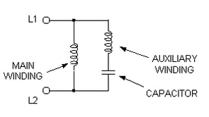
Permanent split capacitor (PSC) motors use a capacitor in one of the windings to increase the current lag between the two windings to make the rotor turn. Often one winding is called the start winding and a run winding. These two windings are used in conjunction with a capacitor to help provide more starting torque and it also helps correct the power factor of the motor. In both technologies, there are varying degrees if inefficiencies because of the way the fields are created/controlled through their coils. Also, there is a physical counter force created by fields on their own coils! These are due to eddy currents (or circular currents of magnetic force) and they increase the inefficiency in the motors.
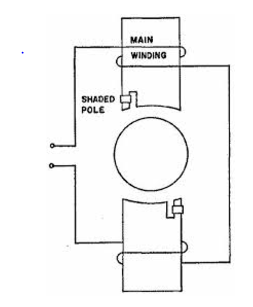 Figure 1. Shaded Pole Figure 1. Shaded Pole |
Figure 2. Permanent Split Capacitor |
Traditionally these motors use a form of mechanical commutation (the moving part of the motor that switches current through the windings). You can almost think of this as the timing component of the motor. This mechanical commutation introduces additional inefficiencies depending on the type of commutator (or electronic switch).
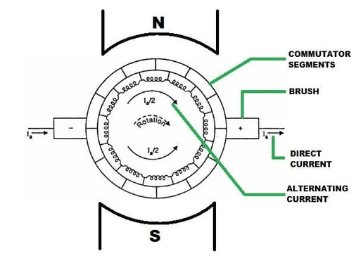 Figure 3. https://en.wikipedia.org/wiki/Commutator_(electric)
Above you can see how the current is fed into the windings via the commutator. As the rotor turns, a set of brushes contact varying windings allowing those windings to build a magnetic field that then pushes off the stator’s magnetic field.
An electronically commutated motor (ECM) uses a microprocessor controller that sequentially energizes/de-energizes each winding of the stator with power to generate an electrical current. Like the other types, this processor-based pulse control builds the magnetic field that causes the rotor inside this ring of magnets to turn; but unlike the others, the microprocessor is using a closed loop feedback mechanism to more precisely control the magnetic fields as to minimize the eddy currents and losses used by traditional mechanically commutated motors. This allows a brushless motor to be able to be used, thus reducing points of physical contact within the moving components of the motor.
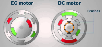 Figure 4. ECM versus PSC
ECM - Increased Efficiency Due to Better Control
In addition to not needing the brushes, this microprocessor brings an efficiency advantage through its controllability of the motor. This gives them a better turn down efficiency than PSC of the equivalent size. ECMs are great at bringing the benefits of modulating to a controlling sensor or variable such as airflow (CFM), torque, or rpm into a small package. The microprocessor is programmed by the manufacturer to the design parameter and it will modulate to retain that constant parameter. If the motor is programmed for constant airflow, for example, and the motor senses a reduction in CFM due to dirty filters, the motor will speed up to hold the programmed design airflow. If, however, the static pressure in the system is reduced, the motor will slow down. Matching the speed of the motor to the design parameters enables the motor to operate as efficiently as possible.
Applications for ECM
EC motors are very valuable for small motor sizes, where a variable frequency drive (VFD) is not cost-effective. They are also great for installations where constant design flow is required because the motor design is more efficient. For larger motors where the parameters fluctuate (such as VAV or VRF systems), a VFD can vary the motor speed to match the variable load. In these applications, the efficiencies of the inner workings of the motor are the driving force behind the energy savings.

