For a recent commissioning project, part of our scope of work was to test an emergency power system for a data center. Because this data center was a very important part of the client company’s work, the system and all components needed to work as intended by the design, and it was crucial that it be tested with all aspects involved before the data center was utilized. This was to ensure there would be no loss of power to the data center servers if any issues were identified. In order to properly test this mission critical system, we not only needed to understand how each component worked, but we also needed to put together full testing documents that included the relationship between all of the components. To make the entire process more fluent, we suggested a coordinated effort for creating documents and testing the system.
Testing Components
This emergency power system utilizes several steps of redundancy and included the following equipment:
- Two generators – The primary generator provides backup power for the entire facility while the secondary generator provides backup power to the mission critical components should the primary generator fail.
- Automatic transfer switches (ATS) – Switches the load if there is more than one power source. In this case, the ATS was used for switching the load to each generator upon a loss of normal power. An ATS will have a slight time delay when it changes. This can be adjusted, but it’s important to know that there is a moment of no power. For the data center, the servers are relying on the uninterruptible power supplies (UPS) during this period with no power from the generator.
- A redundant uninterruptible power supply (UPS) - Using a battery, a UPS will provide emergency power to a load without any interruption (hence the name). There were two to create redundancy.
- Because the redundant UPS systems must be truly uninterrupted on a failure of one, the switch from one to the other is accomplished by a static transfer switch (STS). An STS is essentially a very fast ATS, capable of switching from one UPS to the other in approximately 4 ms.
- In addition to the parts listed above, the HVAC system associated with the data center space is another key component to the emergency power system. Without air conditioning, a server could overheat and fail. For this building, there was a redundant HVAC system.
Testing Process
The testing process included failing or interrupting each type of power source through the entire sequence in a step-wise, coordinated fashion. Similar to functional performance testing of an HVAC system, this kind of testing required a significant amount of preparation. Because there are multiple components that were occurring simultaneously or were dependent on one another, we chose to convey this testing as a flow chart rather than a written outline. Additionally, the testing involved many different team members – Cx Associates, mechanical controls contractor, electrician, representative from ATS/STS manufacturer, electrical engineer, and the generator service technician. Each person was responsible for a certain component in the system.
The following briefly outlines how the testing was done with the associated flow chart diagram:
ATS/Generator #1
The first step was to interrupt utility power and verify that Generator #1 takes over (switch occurring with the ATS).
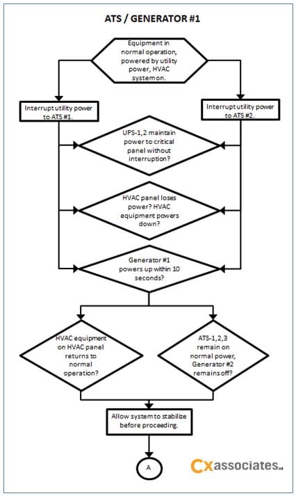 ATS/Generator #1 Testing Flow Chart
Generator #2
After Generator #1 successfully took over, the next step was to fail Generator #1 and verify that Generator #2 takes over (switch occurring with the ATS as well).
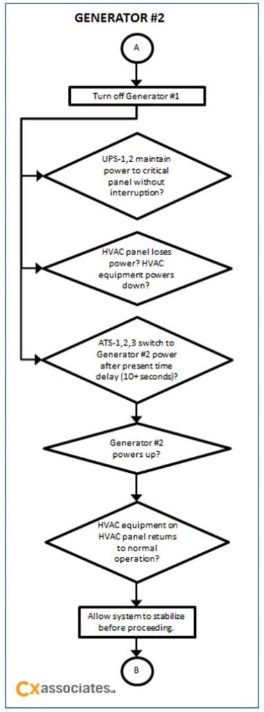 Generator #2 Testing Flow Chart
Redundant UPS
After Generator #2 took over, we failed this generator and tested the UPS system. Because the UPS is run off of a battery, this could not be utilized as the main source of power to the critical data center panel for a long period of time. At this point, the main objective for the facility is to get one of the generators back up and running. The UPS is also redundant, therefore each were tested separately by failing one then the other.
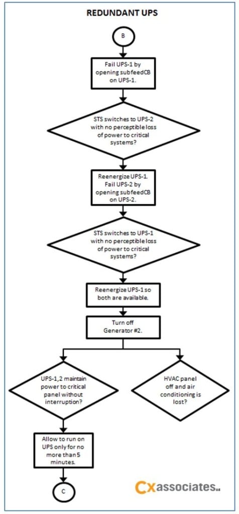 Redundant UPS Testing Flow Chart
Throughout this testing, we verified that the HVAC systems were performing as intended. During each test, it was crucial to verify that the UPS continued to maintain power to the critical panel serving the data center. The flow chart proved to be a very helpful resource during the testing process because it was easy to follow the steps. Our goal is that this flow chart sequence will be a useful tool for the owner when they retest the system on an annual basis to ensure it is still functioning correctly.